Microbore Heating Systems.
by Dr Lisa Blake, Technical Manager, Sava
with comments on reporting from Phil Parnham MRICS, Director, BlueBox Partners
Many heating systems in the UK still use microbore piping. Here, we take a look at the advantages and disadvantages of microbore piping and how best to report on it.
History of microbore piping
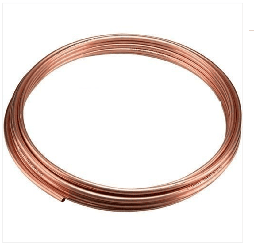
Microbore pipes were introduced in the 1970s and were hailed as an innovative plumbing material for central heating systems. The piping comes on rolls and consists of copper pipe with a thickness between 8 mm and 10 mm. The narrow pipe was flexible enough to be gently bent by hand, reducing the need for joints and soldering which can cause additional heat loss and leakage. This meant that installing the pipe-work for a central heating system could be regarded as a DIY task, saving the homeowner time and money.
More recently, as the price of copper has increased, and we are more environmentally aware, there is renewed interest in microbore piping.

Figure 1 – coil of copper micro-bore pipe
How does microbore differ from conventional systems?
Microbore piping is not only flexible and easy to install, but the narrower pipes also use less water. This means that microbore heating systems need less boiler heat and a smaller capacity boiler can be used. The reduced surface area of the pipes also means less heat loss. Microbore systems are always two-pipe systems using the flow and return convention. Traditional older systems can often be one-pipe systems, where the heat flow from the boiler is one continuous loop.
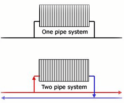
Figure 2 – one and two-pipe systems
Microbore heating systems often have both the flow and return on the same side of the radiator (twin entry valves). These valves further reduce costs by economising on the pipework. Traditional systems tend to have bottom opposite end (BOE) connections, where the water goes into and comes out of the radiator at either end of the bottom of the radiator.
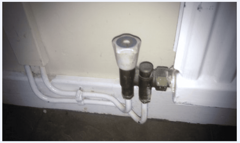
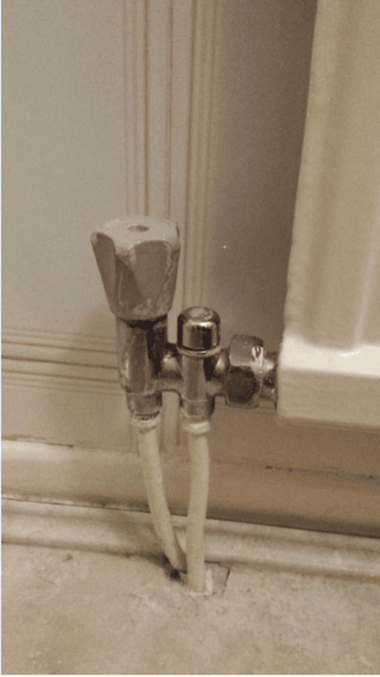
Figure 3 – Twin entry valves
These twin entry valves take hot water from the boiler, which is then piped to the other end of the radiator through a length of 10mm pipe (spreader pipe). The spreader pipe ensures hot water circulates throughout the whole radiator. The spreader pipe is surrounded by another pipe with a wider diameter, which doesn’t extend as far into the radiator. This is called the return pipe. The cooler water from the bottom of the radiator is returned to the boiler via the return tube attached to the valve.
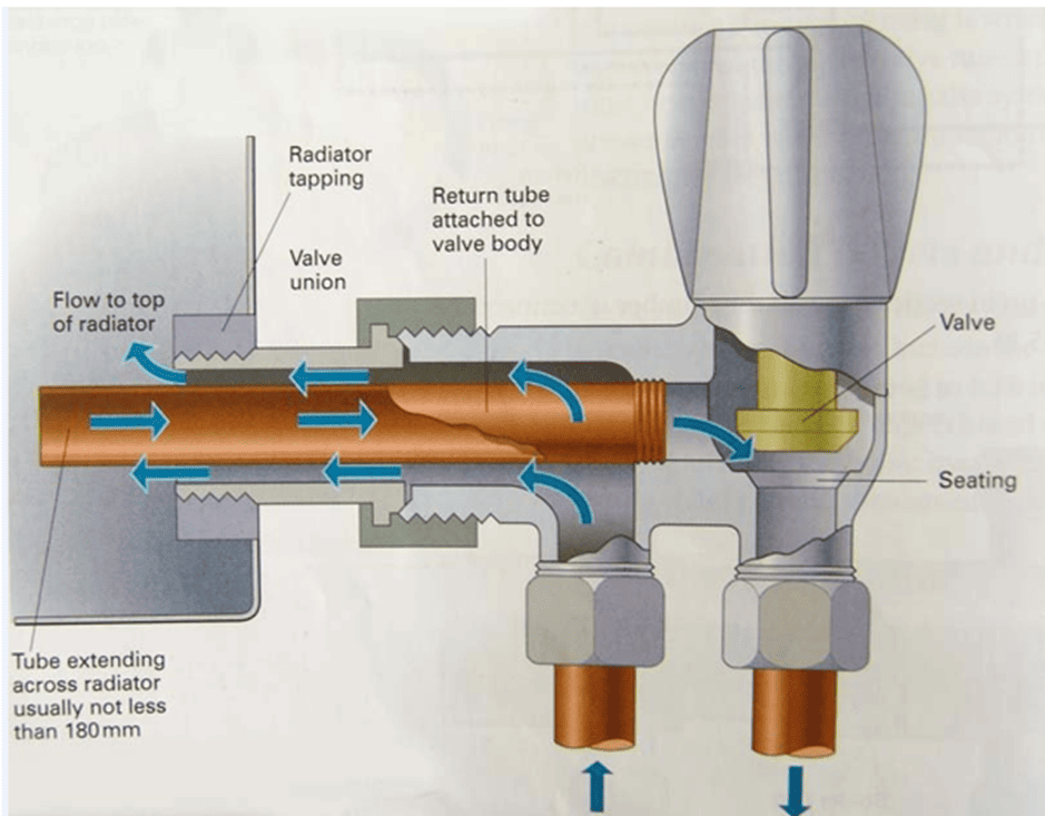
Figure 4 – Twin entry valve – flow and return
As more people changed to double radiators, the twin entry valves were often replaced with BOE, as the spreader pipe would have nowhere to go. In addition, if the new radiator has back tappings (the inlet of the radiator where the valves will be screwed), the twin entry system can’t be used as this required end tappings. The microbore system connects the radiators using a flow manifold and a return manifold, similar to underfloor heating. Generally, it uses one set of manifolds for each floor. With the narrow microbore piping, the manifold must be within about 5m of each radiator and are usually installed under floor boards or in the airing cupboard. The manifold is fed by 22mm pipes from the boiler and the 8 or 10mm microbore piping then goes to the radiators.
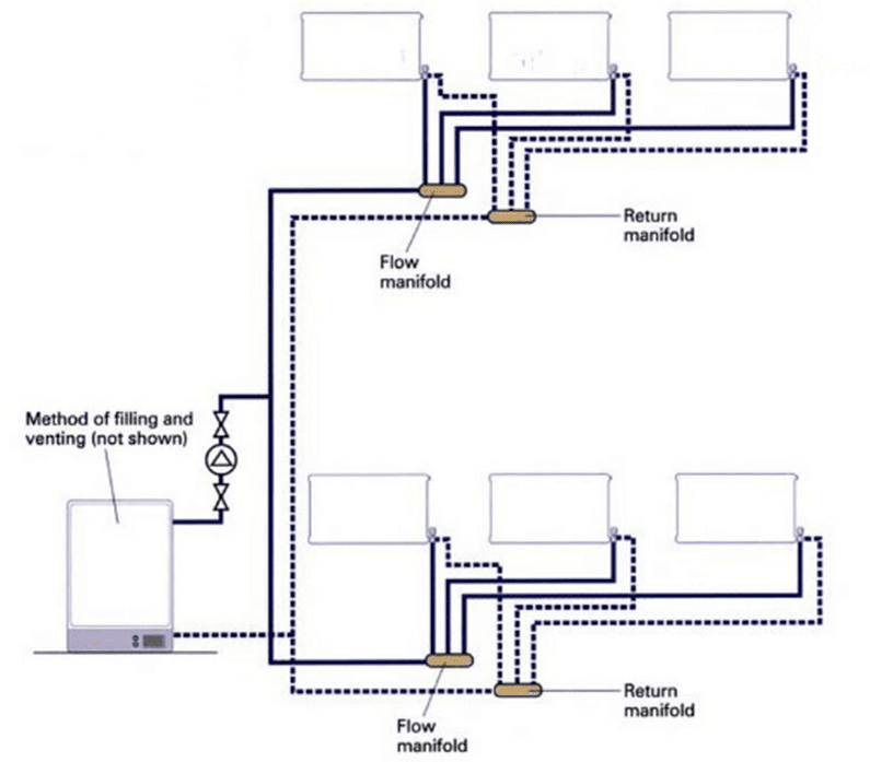
Figure 5 – radiators connected to manifolds
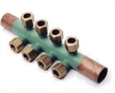
Figure 6 – microbore manifold
Modern microbore
Microbore as a heating application has pretty much gone full circle, particularly since the introduction of plastic ‘speedfit’ pipework. Over the last 10 years, ‘speedfit’ pipework has become commonplace on new build property for similar reasons to the copper version during the ’70s. It comes on a coil, is easy to manipulate, has a smaller diameter meaning it’s less invasive to existing joists and can be more easily contained in the wall structure to ensure there is no visible pipework. ‘Speedfit’ technology also makes effecting a firm water tight connection much easier and removes the need for a blowlamp. The ‘speedfit’ is less prone to kinks or dents and, as it is plastic, less prone to build up of sediment.
How does ‘speedfit’ work?
The ’speedfit’ pipework connects the boiler to the radiators in the same way as copper microbore – by using manifolds. On these type of installs, there should be at least 600mm of copper pipe from the boiler before it converts to plastic. If plastic pipework is running down a wall and into the radiator valves, it is good working practice to run metallic tape down the length of pipework. This is so that, once covered by plaster and decoration, a home owner can use an electrical checker to establish where the pipe is located so they don’t inadvertently drill through it when installing a curtain tie back or curtain pole.
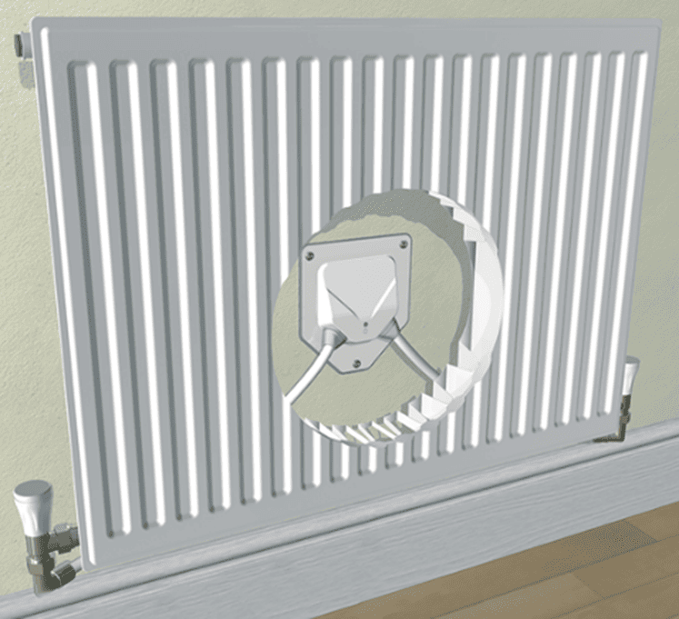
Figure 7 – ‘speedfit’ radiator plate
The ‘speedfit’ radiator valve looks similar to the twin entry valve but is different. The ‘speedfit’ valve is just a standard radiator valve with the pipe entry point horizonal rather than vertical.
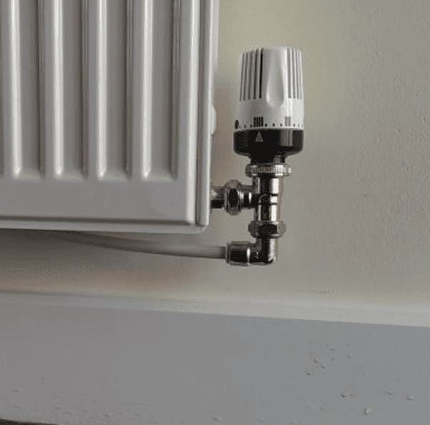
Figure 8 – ‘speedfit’ radiator valve
Issues with microbore systems
If installed correctly and well-maintained, the system can be problem free. It’s vital to use a suitable inhibitor and to flush regularly, ideally by an engineer familiar with microbore systems. A common issue with the microbore system is that it’s only suitable for smaller domestic properties, due to potentially longer pipe runs (greater frictional resistance) and the limited available flow rate, unless more manifolds are used. The smaller pipes can become blocked with internal sediment, particularly in hard water areas. Although the malleable narrow copper pipes make this system easier for DIY installation, they can become kinked easily, which impedes the flow of water and leads to a build-up of sludge and sediment. The copper pipes leading to the radiators are often traced into the wall above the skirting board to avoid ‘hoover bash’.
Reporting on microbore systems
While microbore systems do have a particular set of characteristics, they should be treated like all other carbon-based fuels for assessment and reporting. The most important question to ask the vendor is whether the system has been serviced/inspected by an appropriately qualified person. If authentic looking evidence is produced, then you should consider allocating a condition rating 1 for that particular element. However, if the system hasn’t been serviced or no evidence is produced during your inspection, then a condition rating 3 should be applied. This is because of the potential hazard posed by gas, oil or solid fuel boilers. An installation that can kill should never be rated as a 2 as this gives the wrong message in terms of urgency. Although this ‘1 or 3’ approach is clear for the practitioner, the client could be disappointed with such a minimalist approach. Consequently, you could add a carefully worded phrase that places the client in the right area, such as:
For Gas heating
“The property is heated by a microbore gas central heating system consisting of a boiler in the cupboard on the landing with radiators in every room. There is no evidence that the heating system has been properly installed or serviced within the last twelve months and many of the radiators pipes are dented and bent.”
Condition rating 3 (further investigation).
“Heating installations should be checked and serviced regularly (usually every year) by a registered ‘competent person’ but there was no evidence of this. You should ask an appropriately qualified person to do this before you commit to the purchase and you should not use this boiler until this has been done.”